

マウスを乗せてズームする
371.68
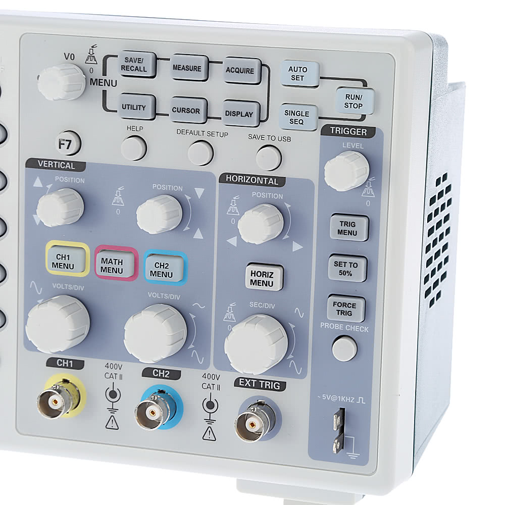
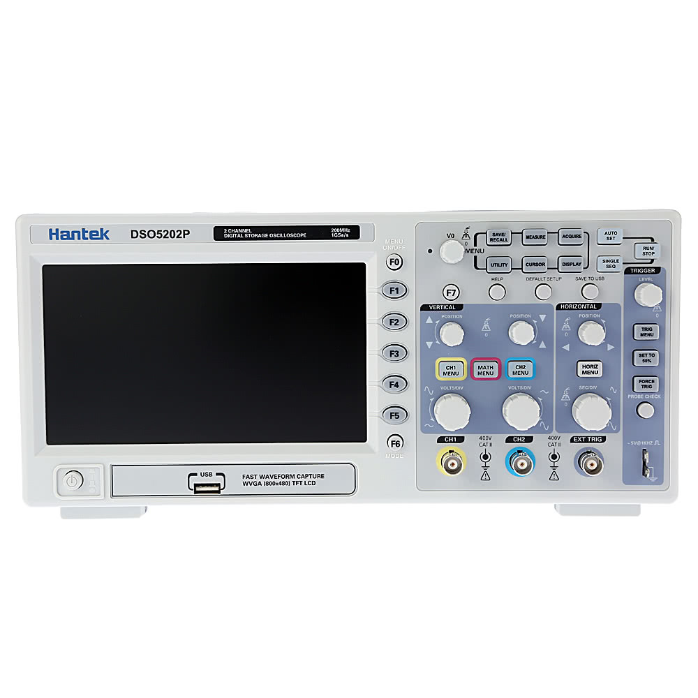
Hantek DSO5202Pプロフェッショナルデジタルストレージオシロスコープ2CH 200MHzの40K 1Gsa / sの色TFTディスプレイ


価格:
US$
372
読み込み中...
配送地域
プラグ:
if the goods arrival in 90 days,we will inform you by email!
Error appeared,Please try again later!
| Model | DSO5202P | |
| Acquisition | ||
| Sample Rate | Real-Time Sample: 1GS/s | |
| Acquisition Modes | ||
| Normal | Normal data only | |
| Peak Detect | High-frequency and random glitch capture | |
| Average | Waveform Average, selectable 4,8,16,32,64,128 | |
| Inputs | ||
| Inputs Coupling | AC, DC, GND | |
| Inputs Impedance | 1MΩ±2% ‖20pF±3pF | |
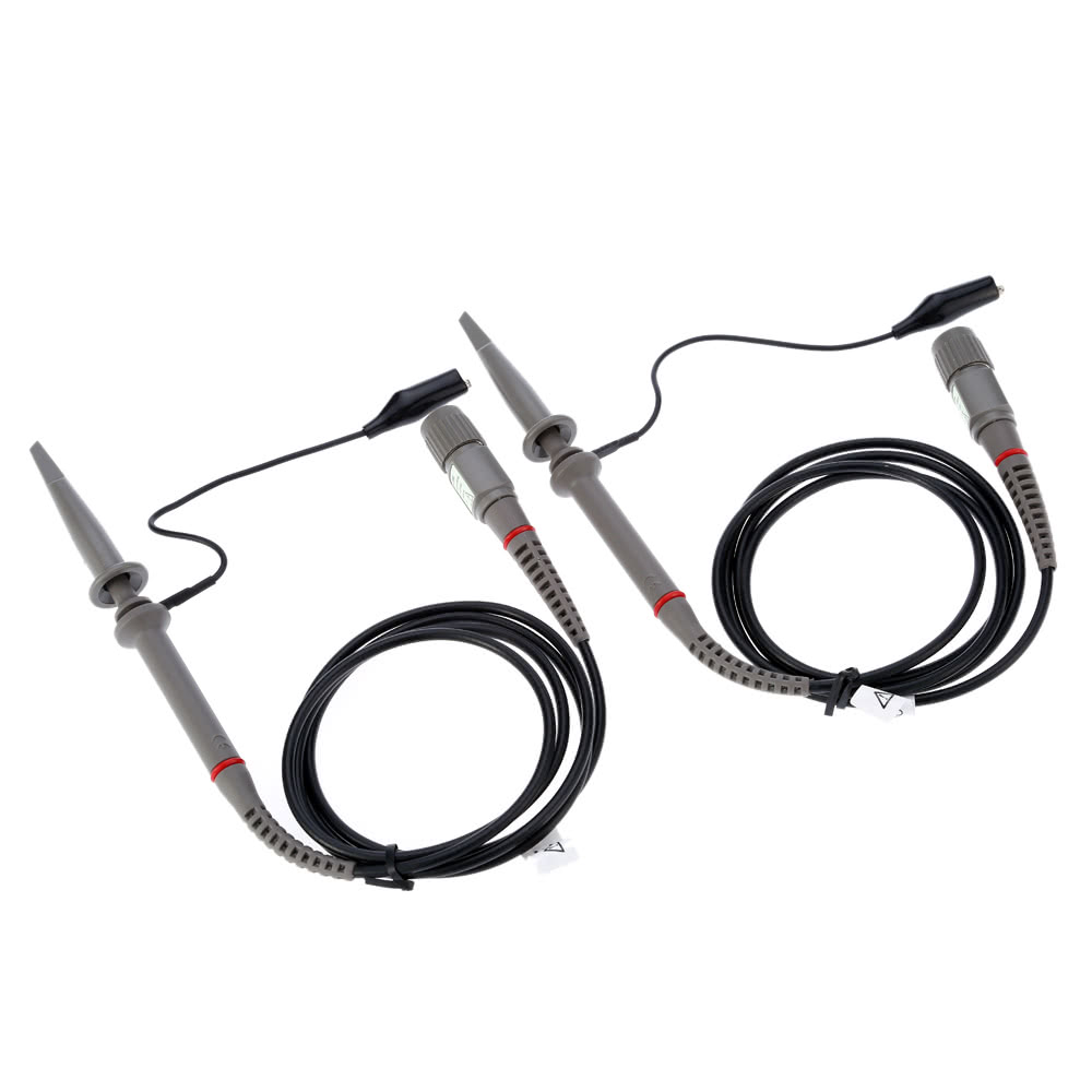
| Probe Attenuation | 1X, 10X | |
| Supported Probe Attenuation Factor | 1X, 10X, 100X, 1000X | |
| Maximum Input Voltage | CAT I and CAT II: 300VRMS (10×), Installation Category; |
|
| Horizontal System | ||
| Sample Rate Range | 500MS/s--1GS/s | |
| Waveform Interpolation | (sin x)/x | |
| Record Length | 40k | |
| SEC/DIV Range | 2ns/div to 40s/div | |
| Sample Rate and Delay Time Accuracy | ±50ppm(at over any ≥1ms time interval) | |
| Position Range | 2ns/div to 10ns/div; (-4div x s/div) to 20ms; |
|
| Delta Time Measurement Accuracy(Full Bandwidth) | Single-shot, Normal mode:± (1 sample interval +100ppm × reading + 0.6ns); >16 averages:± (1 sample interval + 100ppm × reading + 0.4ns); Sample interval = s/div ÷ 200 |
|
| Vertical System | ||
| Vertical Resolution | 8-bit resolution, all channel sampled simultaneously | |
| Position Range | 2mV/div to 10V/div | |
| Bandwidth | 200MHz | |
| Rise Time at BNC(typical) | 1.8ns | |
| Analog Bandwidth in Normal and Average modes at BNC or with probe, DC Coupled | 2mV/div to 20mV/div, ±400mV; 50mV/div to 200mV/div, ±2V 500mV/div to 2V/div, ±40V; 5V/div, ±50V |
|
| Math | +, -, *, /, FFT | |
| FFT | Windows:Hanning,Flatop, Rectamgular,Bartlett,Blackman; 1024 sample point |
|
| Bandwidth Limit | 20MHz | |
| Low Frequency Response(-3db) | ≤10Hz at BNC | |
| DC Gain Accuracy | ±3% for Normal or Average acquisition mode, 5V/div to 10mV/div; ±4% for Normal or Average acquisition mode, 5mV/div to 2mV/div |
|
| DC Measurement Accuracy, Average Acquisition Mode | When vertical displacement is zero, and N ≥16:± (3% × reading + 0.1div + 1mV) only 10mV/div or greater is selected; When vertical displacement is not zero, and N≥16: ± [3% × (reading + vertical position) + 1% of vertical position + 0.2div]; Add 2mV for settings from 2mV/div to 200mV/div; add 50mV for settings from 200mV/div to 5V/div |
|
| Volts Measurement Repeatability, Average Acquisition Mode | Delta volts between any two averages of ≥16 waveforms acquired under same setup and ambient conditions | |
| Trigger System | ||
| Trigger Types | Edge, Video, Pulse, Slope, Over time, Alternative | |
| Trigger Source | CH1, CH2, EXT, EXT/5, AC Line | |
| Trigger Modes | Auto, Normal, Single | |
| Coupling Type | DC, AC, Noise Reject, HF Reject, LF Reject | |
| Trigger Sensitivity(Edge Trigger Type) | DC(CH1,CH2): 1div from DC to 10MHz;1.5div from 10MHz to 100MHz; 2div from 100MHz to Full; DC(EXT): 200mV from DC to 100MHz; 350mV from 100MHz to 200MHz; DC(EXT/5): 1V from DC to 100MHz;1.75V from 100MHz to 200MHz; AC: Attenuates signals below 10Hz; HF Reject: Attenuates signals above 80kHz; LF Reject: Same as the DC-coupled limits for frequencies above 150kHz; attenuates signals below 150kHz |
|
| Trigger Level Range | CH1/CH2: ±8 divisions from center of screen; EXT: ±1.2V; EXT/5:±6V |
|
| Trigger Level Accuracy(typical) Accuracy is for signals having rise and fall times >=20ns | CH1/CH2: 0.2div × volts/div within ±4 divisions from center of screen; EXT: ± (6% of setting + 40mV); EXT/5: ± (6% of setting + 200mV); |
|
| Set Level to 50%(typical) | Operates with input signals ≥50Hz | |
| Video Trigger | ||
| Video Trigger Type | CH1, CH2: Peak-to-peak amplitude of 2 divisions; EXT: 400mV; EXT/5: 2V |
|
| Signal Formats and Field Rates, Video Trigger Type | Supports NTSC, PAL and SECAM broadcast systems for any field or any line | |
| Holdoff Range | 100ns ~ 10s | |
| Pulse Width Trigger | ||
| Pulse Width Trigger Mode | Trigger when (< , >, = , or ≠); Positive pulse or Negative pulse | |
| Pulse Width Trigger Point | Equal: The oscilloscope triggers when the trailing edge of the pulse crosses the trigger level. Not Equal: If the pulse is narrower than the specified width, the trigger point is the trailing edge. Otherwise, the oscilloscope triggers when a pulse continues longer than the time specified as the Pulse Width. Less than: The trigger point is the trailing edge. Greater than (also called overtime trigger): The oscilloscope triggers when a pulse continues longer than the time specified as the Pulse Width |
|
| Pulse Width Range | 20ns ~ 10s | |
| Slope Trigger | ||
| Slope Trigger Mode | Trigger when (< , > , = , or ≠ ); Positive slope or Negative slope | |
| Slope Trigger Point | Equal: The oscilloscope triggers when the waveform slope is equal to the set slope. Not Equal: The oscilloscope triggers when the waveform slope is not equal to the set slope. Less than: The oscilloscope triggers when the waveform slope is less than the set slope. Greater than: The oscilloscope triggers when the waveform slope is greater than the set slope. |
|
| Time Range | 20ns ~ 10s | |
| Overtime Trigger | ||
| Over Time Mode | Rising edge or Falling edge | |
| Time Range | 20ns ~ 10s | |
| Alternative Trigger | ||
| Trigger on CH1 | Internal Trigger: Edge, Pulse Width, Video, Slope | |
| Trigger on CH2 | Internal Trigger: Edge, Pulse Width, Video, Slope | |
| Trigger Frequency Counter | ||
| Readout Resolution | 6 digits | |
| Accuracy (typical) | ±30ppm (including all frequency reference errors and ±1 count errors) | |
| Frequency Range | AC coupled, from 4Hz minimum to rated bandwidth | |
| Signal Source | Pulse Width or Edge Trigger modes: all available trigger sources The Frequency Counter measures trigger source at all times, including when the oscilloscope acquisition pauses due to changes in the run status, or acquisition of a single shot event has completed. Pulse Width Trigger mode: The oscilloscope counts pulses of significant magnitude inside the 1s measurement window that qualify as triggerable events, such as narrow pulses in a PWM pulse train if set to < mode and the width is set to a relatively small time. Edge Trigger mode: The oscilloscope counts all edges of sufficient magnitude and correct polarity. Video Trigger mode: The Frequency Counter does not work. |
|
| Measurement | ||
| Cursor Measurement | Voltage difference between cursors: △V Time difference between cursors: △T Reciprocal of △T in Hertz (1/ΔT) |
|
| Auto Measurement | Frequency, Period, Mean, Pk-Pk, Cycli RMS, Minimum, Maximum, Rise time, Fall Time, +Pulse Width, -Pulse Width, Delay1-2Rise, Delay1-2Fall, +Duty, -Duty, Vbase, Vtop, Vmid, Vamp, Overshoot, Preshoot, Period Mean, Period RMS, FOVShoot, RPREShoot, BWIDTH, FRF, FFR, LRR, LRF, LFR, LFF | |
| Display | ||
| Display Type | 7 inch 64K color TFT (diagonal liquid crystal) | |
| Display Resolution | 800 horizontal by 480 vertical pixels | |
| Display Contrast | Adjustable (16 gears) with the progress bar | |
| Probe Compensator Output | ||
| Output Voltage (typical) | About 5Vpp into ≥1MΩ load | |
| Frequency(typical) | 1kHz | |
| Power Supply | ||
| Supply Voltage | 100-120VACRMS(±10%), 45Hz to 440Hz, CATⅡ 120-240VACRMS(±10%), 45Hz to 66Hz, CATⅡ |
|
| Power Consumption | <30W | |
| Fuse | 2A, T rating, 250V | |
| Environmental | ||
| Temperature | Operating: 32℉ to 122℉ (0℃ to 50℃); Non-operating: -40℉ to 159.8℉ (-40℃ to +71℃) |
|
| Cooling Method | Convection | |
| Humidity | +104℉ or below (+40℃ or below): ≤90% relative humidity; 106℉ to 122℉ (+41℃ to 50℃): ≤60% relative humidity |
|
| Altitude | Operating: Below 3,000m (10,000 feet); Non-operating: Below 15,000m(50,000 feet) |
|
Q & A
ディスカッション
TOMTOPフォーラムはアイデア交換の場であり、ITエンジニアがディスカッションに参加するのを助けるコミュニティです。一方、TomTopカスタマーサービス(Tomtopカスタマーサービスアイコン付き)は、httpの連絡先と同じ機能でタイムリーに対応します ://www.tomtop.com/contacts
このフォーラムを全面的に開くレビューする方がまだいません
ご感想が聞かせると、TOMTOPポイントが手に入れます。前5位はTOMTOPポイントが二倍になります。
レビューする


